Have you ever dreamt of a keyless entry system, tailored precisely to your needs, that you built with your own hands? The world of smart home technology is more accessible than ever, and creating your own smart lock with an Arduino offers a rewarding blend of learning, customization, and enhanced home security. Forget fumbling for keys or worrying about lost spares; a DIY Arduino smart lock puts you in control, opening up possibilities for unique access methods and intelligent features.
What is a DIY Smart Lock and Why Build One with Arduino?
A DIY smart lock is a custom-built electronic access control system for your door, leveraging the power and flexibility of a microcontroller like Arduino. Unlike off-the-shelf smart locks, a DIY project empowers you to understand the underlying technology, integrate specific features, and design a solution that perfectly fits your home or office.
Building a smart lock with Arduino offers several compelling advantages. Firstly, it’s a fantastic learning experience, delving into electronics, programming, and mechanical integration. Secondly, it provides unparalleled customization. You’re not limited to predefined features; you can choose your preferred unlocking method, add personalized feedback, and even integrate it with other smart home systems. Thirdly, DIY projects can be surprisingly cost-effective compared to purchasing high-end commercial smart locks, as you only buy the necessary components. Finally, the sense of accomplishment from building your own secure access system is truly unmatched. These locks are ideal for personal projects, enhancing security in a home, securing a private office, or even for laboratory access control.
Popular Methods for Arduino Smart Locks
The beauty of Arduino lies in its versatility, allowing for various smart lock implementations. The choice of access method depends on your desired security level, convenience, and technical comfort.
RFID-Based Smart Lock
|
Our Picks for the Best Smart Lock in 2026
As an Amazon Associate I earn from qualifying purchases.
|
||
| Num | Product | Action |
|---|---|---|
| 1 | ULTRALOQ U-Bolt Pro WiFi Smart Lock with Door Sensor, 8-in-1 Keyless Entry Door Lock with Fingerprint ID, App Remote Control, Built-in WiFi Keypad Deadbolt, Auto Unlock, IP65 Waterproof, Easy Install |

|
| 2 | Schlage Encode Smart WiFi Deadbolt Lock for Front Door - Keyless Entry with App or Touchscreen - Works with Alexa, Hey Google, & Airbnb - Create Codes for Guests - Matte Black |
|
| 3 | TEEHO TE001 Keyless Entry Door Lock with Keypad - Smart Deadbolt Lock for Front Door with 2 Keys - Auto Lock - Easy Installation - Matte Black |
|
| 4 | Electronic Passwords Keyless Entry Door Locks Smart Deadbolt Metal Lock Auto Time Delay Locking Secure Durable Low Battery Alert Type-C Port for Emergency Charging |
|
| 5 | TEEHO TE001 Keyless Entry Door Lock with Keypad - Smart Deadbolt Lock for Front Door with 2 Keys - Auto Lock - Easy Installation - Oil-Rubbed Bronze |
|
| 6 | TEEHO TE001 Keyless Entry Door Lock with Keypad - Smart Deadbolt Lock for Front Door with 2 Keys - Auto Lock - Easy Installation - Satin Nickel |
|
| 7 | Philips Wi-Fi Door Lock, WiFi Smart Lock Keyless Entry Deadbolt for Front Door, Compatible with Alexa & Google Assistant, Remote Control, Built-in WiFi, APP Fingerprint Passcode Unlock, Auto Locking |
|
| 8 | eufy Security Smart Lock C220, Fingerprint Keyless Entry Door Lock, Built-in Wi-Fi, App Remote Control, Front Door Smart Deadbolt, IP53 Waterproof, 8-Months Battery, Nickel |
|
| 9 | eufy Security Smart Lock C220, Fingerprint Keyless Entry Door Lock, Built-in Wi-Fi, App Remote Control, Front Door Smart Lock Deadbolt, 8Months Battery, Reliable Power, IP53 Waterproof, BHMA Grade 3 |
|
| 10 | Philips Wi-Fi Door Lock, WiFi Smart Lock Keyless Entry Deadbolt for Front Door, Remote Control, Built-in WiFi, APP Fingerprint Passcode Unlock, Auto Locking |
|
RFID (Radio Frequency Identification) smart locks offer a simple and effective keyless entry. You use an RFID card or tag to gain access, much like a hotel key card or public transit pass. The system typically involves an Arduino board, an RC522 RFID reader, and one or more RFID cards or key fobs. When an authorized card is scanned, the RFID reader communicates with the Arduino, which then triggers a locking mechanism. This method is highly popular due to its straightforward implementation and reliable performance. It’s perfect for those seeking a quick, tap-to-enter solution.
Bluetooth-Controlled Smart Lock
For smartphone-savvy users, a Bluetooth-controlled smart lock provides convenient access directly from your mobile device. This setup utilizes a Bluetooth module (like the HC-05 or HC-06) connected to your Arduino. You can then use a custom app or a generic Bluetooth terminal app on your phone to send commands to the Arduino, which in turn controls the lock. This method offers the benefit of remote access within Bluetooth range and eliminates the need for physical cards. It’s a great choice for tech enthusiasts who prefer controlling their devices through a smartphone interface.
Keypad/Password Smart Lock
A keypad-based smart lock is a classic and robust solution, requiring users to enter a specific PIN code to unlock the door. This system typically includes a numeric keypad, an Arduino, and often an LCD display for user feedback. The Arduino reads the input from the keypad, verifies the code against a stored password, and then activates the lock. This method is widely understood and doesn’t require any special fobs or a smartphone, making it a reliable option for various users. It provides a familiar and secure way to manage access without physical keys.
Fingerprint Smart Lock
For enhanced biometric security, a fingerprint smart lock adds an advanced layer of protection. This sophisticated system integrates a fingerprint sensor with your Arduino, allowing access only to registered individuals whose fingerprints are recognized. While more complex to implement and potentially more expensive due to the sensor, fingerprint access offers a high level of security and convenience, eliminating the need for keys or codes. It’s an excellent option for those looking for cutting-edge personal security.
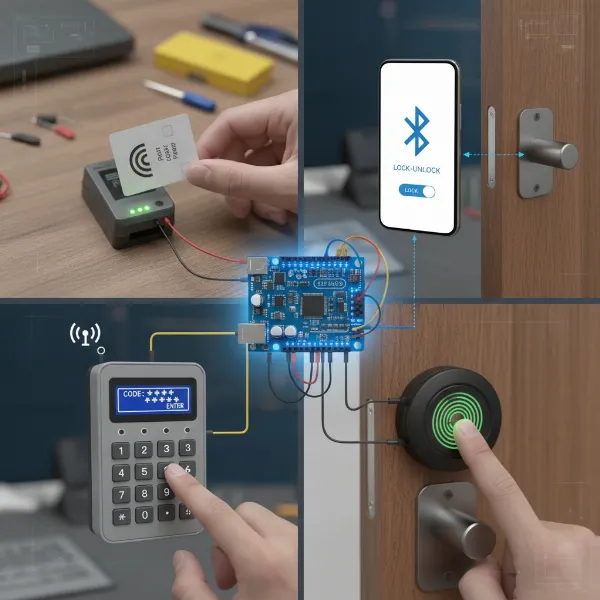 Various DIY Arduino smart lock access methods including RFID, Bluetooth, keypad, and fingerprint sensor.
Choosing the Right Components for Your DIY Arduino Smart Lock
Building your smart lock begins with selecting the appropriate hardware. Each component plays a vital role in the system’s functionality, security, and user experience. Thoughtful selection ensures a robust and reliable smart lock.
The Brain: Arduino Board
The Arduino board is the central processing unit of your smart lock.
- Arduino Uno: A popular choice for beginners, offering sufficient digital and analog pins, processing power, and a large community for support. It’s robust and easy to work with.
- Arduino Nano: A smaller, more compact version of the Uno, ideal for projects where space is limited. It offers similar functionality in a smaller footprint.
- ESP32/ESP8266: While not strictly Arduino boards (though programmable with the Arduino IDE), these microcontrollers offer integrated Wi-Fi and Bluetooth, making them excellent for adding IoT capabilities like remote monitoring or control via the internet. They are more advanced but provide greater connectivity.
The Lock Mechanism: Servo Motor vs. Solenoid Lock
The actuator physically locks and unlocks your door.
- Servo Motor: A common choice for DIY projects due to its precise control over angular position. A small servo can be adapted to manipulate an existing deadbolt or slide lock. They are relatively quiet and consume less power, making them suitable for battery-operated solutions.
- Solenoid Lock: A more robust and often preferred option for actual door security. Solenoid locks are typically fail-safe (unlock on power loss) or fail-secure (lock on power loss) and require a relay module to interface with the Arduino, as they usually operate at higher voltages (e.g., 12V) and currents. They provide a more definitive locking action.
User Interface/Input
This is how you interact with your smart lock.
- RFID Reader (e.g., RC522): For RFID-based systems, this module reads the unique identification data from RFID tags. It connects to the Arduino via SPI (Serial Peripheral Interface).
- Bluetooth Module (e.g., HC-05/HC-06): For Bluetooth control, this module enables wireless communication between your Arduino and a smartphone or other Bluetooth-enabled device. It typically connects via UART (Universal Asynchronous Receiver-Transmitter).
- Keypad: A 4×4 or 3×4 matrix keypad is used for password-based systems. It connects to digital pins on the Arduino and is read using a keypad library.
- Fingerprint Sensor: For biometric authentication, modules like the GT-511C3 or R307 fingerprint sensor can be integrated. These sensors typically communicate via UART.
Feedback & Power
Providing visual or auditory cues and a stable power source are crucial.
- 16×2 I2C LCD Display: A small liquid crystal display is highly useful for providing feedback such as “Access Granted,” “Door Locked,” or “Enter PIN.” The I2C interface simplifies wiring with only two data pins (SDA, SCL) and power.
- LEDs (Red/Green): Simple and effective for indicating lock status (e.g., green for unlocked, red for locked) or access status.
- Buzzer: An audible indicator for successful unlocks, incorrect attempts, or other alerts.
- Power Supply: A stable 5V power supply for the Arduino and most modules is essential. If using a solenoid lock or a more powerful servo, a separate 12V power adapter and a voltage regulator (for the Arduino) might be required. A battery pack (e.g., 9V or multiple 3.7V Li-ion cells) can make your project portable.
Wiring & Construction
- Jumper Wires: Essential for connecting components on a breadboard or directly to the Arduino.
- Breadboard: Useful for prototyping and testing circuits before final assembly.
- Enclosure: A custom-made enclosure (3D printed, laser-cut, or even cardboard) protects the electronics and gives your smart lock a professional finish.
“The true power of DIY smart locks isn’t just in their functionality, but in the deeper understanding they foster. You’re not just a user; you become an innovator and problem-solver.” – Dr. Alistair Finch, Robotics & Electronics Educator.
Step-by-Step: Building Your First Arduino Smart Lock (RFID Example)
Let’s walk through building a common RFID-based smart lock. This example will guide you through the process from gathering materials to testing.
Gathering Materials
For a basic RFID smart lock with an LCD display, you’ll typically need:
- Arduino Uno or Nano board
- RC522 RFID Reader module
- RFID cards/tags
- 16×2 I2C LCD Display
- SG90 or standard Servo Motor (or Solenoid Lock with a 5V/12V Relay Module)
- Jumper wires (Male-to-Male and Male-to-Female)
- Breadboard
- 5V Power Supply (and potentially a 12V supply for a solenoid lock)
- A suitable physical lock mechanism (e.g., a small slide bolt or deadbolt) to be actuated by the servo/solenoid.
Circuit Assembly (Wiring Diagram Overview)
Connecting your components correctly is paramount. While detailed diagrams vary, here’s a general guide for an RFID-based system:
- Arduino Power: Connect the Arduino to a 5V power supply.
- RFID Reader (RC522):
- VCC to Arduino 3.3V
- GND to Arduino GND
- RST to Arduino Digital Pin 9
- SDA (SS) to Arduino Digital Pin 10
- MOSI to Arduino Digital Pin 11
- MISO to Arduino Digital Pin 12
- SCK to Arduino Digital Pin 13
- 16×2 I2C LCD Display:
- VCC to Arduino 5V
- GND to Arduino GND
- SDA to Arduino Analog Pin A4
- SCL to Arduino Analog Pin A5
- Servo Motor:
- Brown wire (GND) to Arduino GND
- Red wire (VCC) to Arduino 5V
- Orange wire (Signal) to Arduino Digital Pin (e.g., Pin 3)
- Solenoid Lock (if used, with Relay Module):
- Relay VCC to Arduino 5V
- Relay GND to Arduino GND
- Relay Signal pin to Arduino Digital Pin (e.g., Pin 8)
- Connect the Solenoid Lock to the relay’s NO (Normally Open) and Common terminals, and provide external 12V power to the solenoid via the relay.
Always double-check your connections against a specific circuit diagram to prevent damage to components.
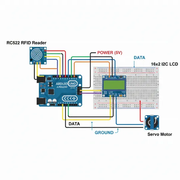 A detailed wiring diagram showing an Arduino Uno connected to an RC522 RFID reader, LCD, and servo motor.
Programming the Arduino
This step involves writing and uploading the code that defines your smart lock’s logic.
- Arduino IDE Setup: Download and install the Arduino IDE on your computer.
- Library Installation: You will need libraries for your components. For an RFID system, typically
MFRC522.handLiquidCrystal_I2C.h. Go toSketch > Include Library > Manage Libraries...in the Arduino IDE and search for and install the necessary libraries. - UID Enrollment Code: Before writing the main lock code, you need to identify the unique IDs (UIDs) of your RFID cards. Upload a simple “RFID_UID_Reader” sketch (often found in the
MFRC522library examples) to your Arduino. Open the Serial Monitor, scan your RFID cards, and note down their UIDs. These UIDs will be programmed into your main smart lock code as authorized access credentials. - Main Smart Lock Code: Write your program to:
- Initialize the RFID reader, LCD, and servo/relay.
- Continuously check for a new RFID card present.
- Read the UID of the scanned card.
- Compare the scanned UID with a list of authorized UIDs.
- If authorized, activate the servo/relay to unlock, display “Access Granted” on the LCD, and potentially play a sound.
- If unauthorized, display “Access Denied,” play an error sound, and keep the door locked.
- Implement an auto-lock mechanism after a short delay for security.
- Upload the Code: Select your Arduino board (
Tools > Board) and the correct COM Port (Tools > Port), then click the “Upload” button.
Testing and Calibration
After uploading the code, it’s time to test your system.
- Initial Test: Bring an authorized RFID card close to the reader. The lock mechanism should activate, and the LCD should display “Access Granted” and “Door Unlocked.” Test with an unauthorized card to ensure it denies access.
- Mechanical Calibration: Adjust the servo’s angles or the solenoid’s positioning to ensure it reliably engages and disengages the physical lock without jamming.
- Timing: Fine-tune delays in your code (e.g., how long the door stays unlocked) for optimal user experience and security.
Enclosure and Mounting
Once your electronics work flawlessly, create a protective enclosure. This can be as simple as a cardboard box or a more durable 3D-printed case. Mount the components securely within the enclosure, ensuring the RFID reader (or keypad/sensor) is accessible, and the servo/solenoid is correctly linked to your door’s existing lock mechanism. Consider the aesthetics and durability, especially if exposed to daily use.
Enhancing Your DIY Smart Lock
Your basic Arduino smart lock is just the beginning. The modular nature of Arduino projects allows for numerous enhancements to boost functionality, convenience, and security.
- Adding an LCD for Status Messages: As seen in our RFID example, an LCD is invaluable for user feedback. It can display “Scanning…”, “Access Granted”, “Access Denied”, “Door Locked”, or “Enter PIN”, guiding users through the process.
- Integrating Wi-Fi (using ESP modules): By swapping your Arduino Uno/Nano for an ESP32 or ESP8266, you can add Wi-Fi connectivity. This allows for remote control of your lock via the internet, push notifications to your phone when someone tries to enter, or even logging access attempts to a cloud server.
- Battery Backup System: To ensure your smart lock functions during power outages, integrate a small uninterruptible power supply (UPS) using rechargeable batteries (e.g., Li-ion) and a charging module. This provides continuous operation and peace of mind.
- Advanced Authentication Methods: Combine multiple access methods for increased security. For example, require both an RFID card and a correct PIN entry, or a fingerprint scan plus a password. This multi-factor authentication significantly strengthens your lock’s resilience against unauthorized access.
- Security Considerations: Always think about the robustness of your design.
- Physical Tampering: Design your enclosure to be tamper-resistant.
- Code Robustness: Ensure your code handles edge cases, includes error checking, and stores sensitive data (like UIDs or PINs) securely, avoiding plain text. Regularly update your code with new security practices.
- Power Supply Security: Protect wiring from being easily cut or shorted.
Conclusion
Building your own DIY smart lock with Arduino is an incredibly rewarding project, offering a unique blend of practical home security and engaging electronics education. From the fundamental principles of RFID and Bluetooth control to the satisfaction of seeing your custom code bring a physical lock to life, you gain invaluable skills and a tailored security solution. The journey empowers you to create a system that perfectly matches your needs, reflecting your expertise and creativity.
So, are you ready to take control of your home security and transform your entry experience with your own innovation?